Precise CSI Measurement with COTS Wi-Fi devicesParticipants: Yiwei Zhuo, Qinghao Liu, Hongzi ZhuSponsors: LION |
|
|
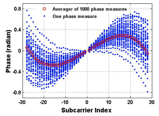
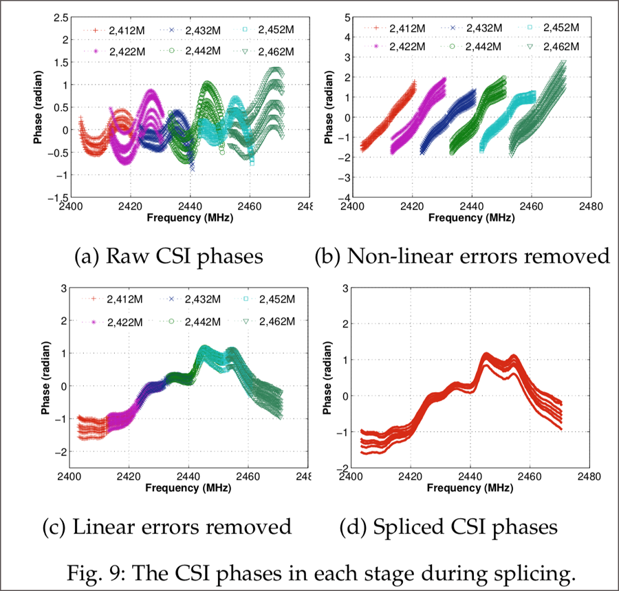
WiFi technology has gained a wide prevalence for not only wireless communication but also pervasive sensing. A wide variety of emerging applications leverage accurate measurements of the Channel State Information (CSI) information obtained from commodity WiFi devices. Due to hardware im-perfection of commodity WiFi devices, the frequency response of internal signal processing circuit is mixed with the real channel frequency response in passband, which makes deriving accurate channel frequency response from CSI measurements a challenging task. In this project, we identify non-negligible non-linear CSI phase errors and report that IQ imbalance is the root source of non-linear CSI phase errors. We conduct intensive analysis on the characteristics of such non-linear errors and find that such errors are prevalent among various WiFi devices. Furthermore, they are rather stable along time and the received signal strength indication (RSSI) but sensitive to frequency bands used between a transmission pair. Based on these key observations, we propose a new CSI splicing method, called π-Splicer, to compensate both non-linear and linear CSI phase errors.
|
|
π-Splicer Tutorial: I. You need first to install the CSI tool from the Wireless And Networked Distributed Sensing (WANDS) system group@NTU, Singapore: Please refer to http://wands.sg/AtherosCSI/ After you complete installation, please check the basic functions of transmission and reception. Probably, in order to record the timestamps of each measurement, you need to replace the original source code in ~/Atheros-CSI-Tool-UserSpace-APP/csi_fun.c from line 141~144 and 152~155 with the code below:
((buf_addr[0] << 56) & 0xff00000000000000) | ((buf_addr[1] << 48) & 0x00ff000000000000) | II.You are free to use our π-Splicer tool following the instructions in below: 1. Download the source code files here. 2. The transmitter needs to scan many channels in a short time. To implement it, please replace the file /Atheros-CSI-Tool-UserSpace-APP/hostapd-2.5/hostapd/hostapd_cli.c with the file /CSI_Modified_Code/Transmitter/hostapd_cli.c . Then make it. Before you use it, there are several things you have to do.
3.The receiver needs to receive packets from the transmitter and log them into a file. For convenience, we print the basic info of each packet received. Please replace the file /Atheros-CSI-Tool-UserSpace-APP/recvCSI/main.c with the file /CSI_Modified_Code/Receiver/main.c . Then make it. Before you run the program, there are several things you need to do.
4. Now you are ready to measure non-linear CSI phase errors. Please follow the instructions below:
sudo iw phy phy0 set antenna 0x1 //bit mask for output sudo iw phy phy0 info | grep -i ant //check sudo ifconfig wlan1 up #wait until connection is established
sudo ./recv_csi Ant_1.dat
sudo ./start_hostapd.sh #(Open a new terminal) cd Atheros-CSI-Tool-UserSpace-APP/hostapd-2.5/hostapd/ sudo ./hostapd_cli chan_switch 3 2412 ht
then it will display Here are the channels you will scan: 1 3 5 7 9 11 2412 2422 2432 2442 2452 2462 If all goes well, you should see the receiver printing packet information on the screen.
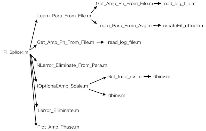
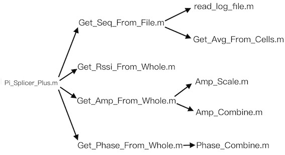
5. The data process program in /CSI_Modified_Code/Data_Process/ (we only write the program for data collected on channel 2412, 2422, 2432, 2442, 2452, 2462MHz. You may need to modify the code based on your own needs). Here is the relationship tree of our source files.
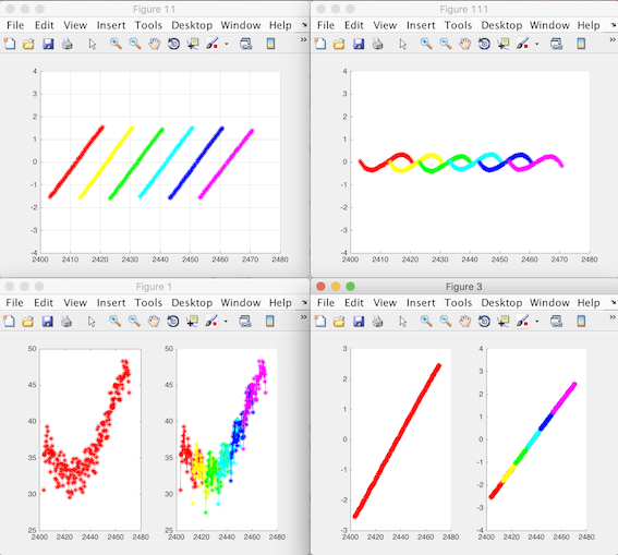
If you have 'Ant_1.dat','Ant_2.dat','Ant_3.dat' three files, you can run the 'Pi_Splicer.m'. You will get the non-linear error parameters of 6 channels of Tx1~Rx1&Rx2&Rx3 in 'Parameter111213.mat'. If there is no problem, you will see 4 figures, Figure111, Figure11, Figure1, Figure3.
In Figure111, 6 sine-shape curves are plotted, which illustrate the non-linear error on each channel. Figure11 plots the results with non-linear phase errors removed. In Figure1, you will see two subplots. The left is the combined amplitudes of six channels with smoothing. The right is the combined amplitudes of each channel without smoothing. In Figure3, you will see two subplots. The left is the combined phases of six channels with smoothing. The right is the combined phase of each channel without smoothing. 6. The program above only applies to data of one loop. If you want to deal with data of multiple loops, please follow the instructions below (similarly, we only write program for the 6 channels mentioned above. You may need to modify the code for your own purpose):
sudo iw phy phy0 set antenna 0x7 sudo ifconfig wlan1 up #wait until the connection is established sudo ./recv_csi tst.dat
then enter 1 2 6 50 10 The receiver will receive about 3000 packets. We average CSI data on each channel (e.g., the number of packets on each channel should be greater than 50).
7. There are several things you should notice:
Here are some notes related to CSI measurement with Intel 5300
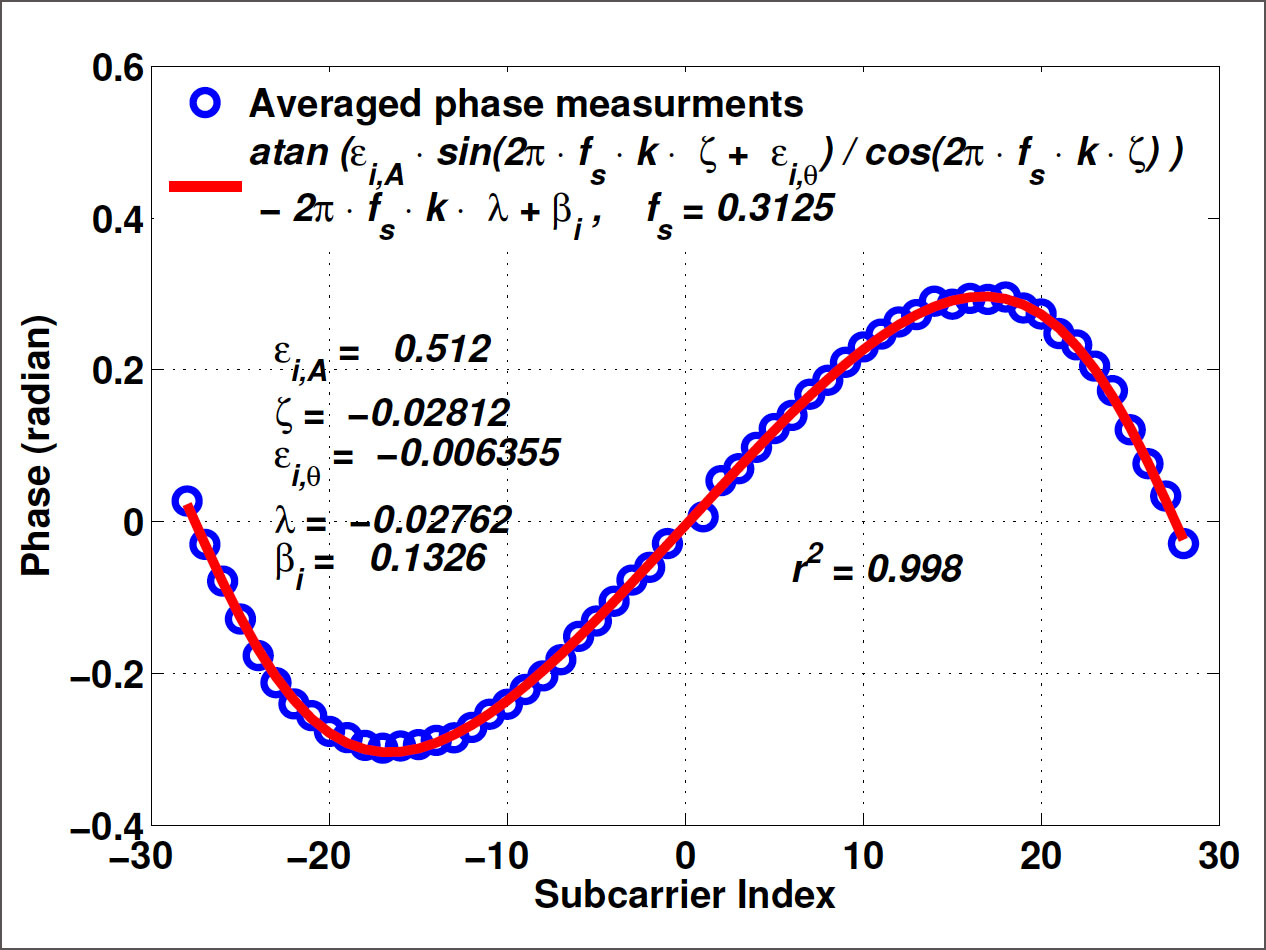
2) It is better to remove the major part of PDD (i.e., subtracting $2 * \pi * k * f_s * i * \tau_s$ from the measured unwrapped CSI phase) before eliminating non-linear phase error. This can greatly reduce the searching space when removing residual linear phase error as described in Subsection 4.2 in the π-Splicer paper.
III. Please refer to the following publications for more details and please cite them if you use π-Splicer in your work.
|
|
|
Yiwei Zhuo, Hongzi Zhu, Hua Xue and Shan Chang
in Proceedings of IEEE INFOCOM 2017, Atlanta, GA, USA.
|
|
Hongzi Zhu, Yiwei Zhuo, Qianghao Liu and Shan Chang
IEEE Transactions on Mobile Computing (IEEE TMC), 17(9), pp. 2155-2165, 2018.
|
|
Yiwei Zhuo, Hongzi Zhu and Hua Xue
in Proceedings of IEEE ICPADS 2016, Wuhan, China.
|